本社
〒808-0109福岡県北九州市若松区南二島2丁目6番7号
TEL:093-701-3501
FAX:093-701-3386
PC上のシミュレーションで熱とその流れを「見える化」。 試作品での検証作業を大幅に削減し、 お客様の製品開発を次のステージへと加速させます。
試作機を作らないと、温度分布がわからない
開発の手戻りが多く、時間とコストがかかりすぎている
最適なヒーターの仕様(形状・ワット数・配置)が知りたい
既存装置の熱問題を改善し、性能を向上させたい
新製品の熱設計を、開発の上流工程でFIXさせたい
熱解析とは、コンピュータ上で作成した仮想モデルを使い、熱や流体(空気・水など)の動きをシミュレーションする技術です。
私たちの熱解析は単なる解析サービスではありません。長年、工業用ヒーターを製造してきた「熱のプロ」としての知見を掛け合わせることで、現実に限りなく近い、実用的な解析結果をご提供できるのが最大の強みです。
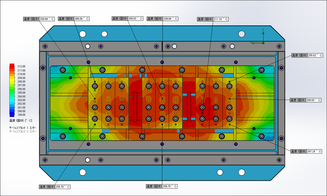
加熱設備設計
ヒーター配置、容量選定、温度分布の均一化を解析により事前評価し、装置の性能向上と省エネ化を実現。加熱ムラや過昇温の要因を可視化し、最適な熱設計をサポートします。
流路設計・流量バランス最適化
内部の流れや流速分布を解析することで、流量の偏り、圧力損失、デッドスペースの発生を事前に把握し、流路形状の最適化が可能になります。均一流路設計に効果を発揮します。
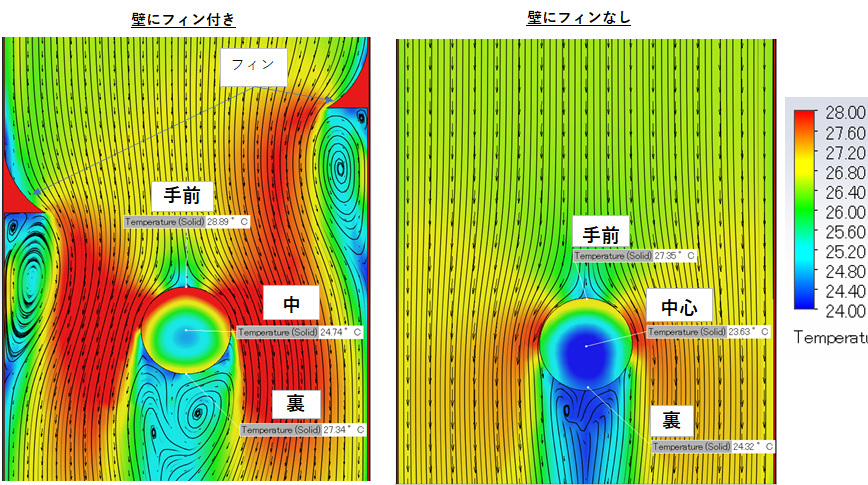
冷却設計・放熱対策
電子機器や金型、発熱部品の冷却性能を解析し、放熱効率改善や過熱防止の設計に活用できます。冷却媒体の流量設定やヒートシンク形状の最適化、温度上昇シミュレーションが可能です。

試作・実験の回数を劇的に削減。
PC上でスピーディに複数パターンの検証が可能になり、開発リードタイムを大幅に短縮します。

試作機の製作費用や、実験にかかる人件費・材料費を削減。手戻りのない効率的な開発プロセスで、トータルコストを圧縮します。

熱分布の最適化や、効率的な冷却方法の発見など、実験だけでは難しかった最適な設計を追求可能に。製品の付加価値向上に貢献します。

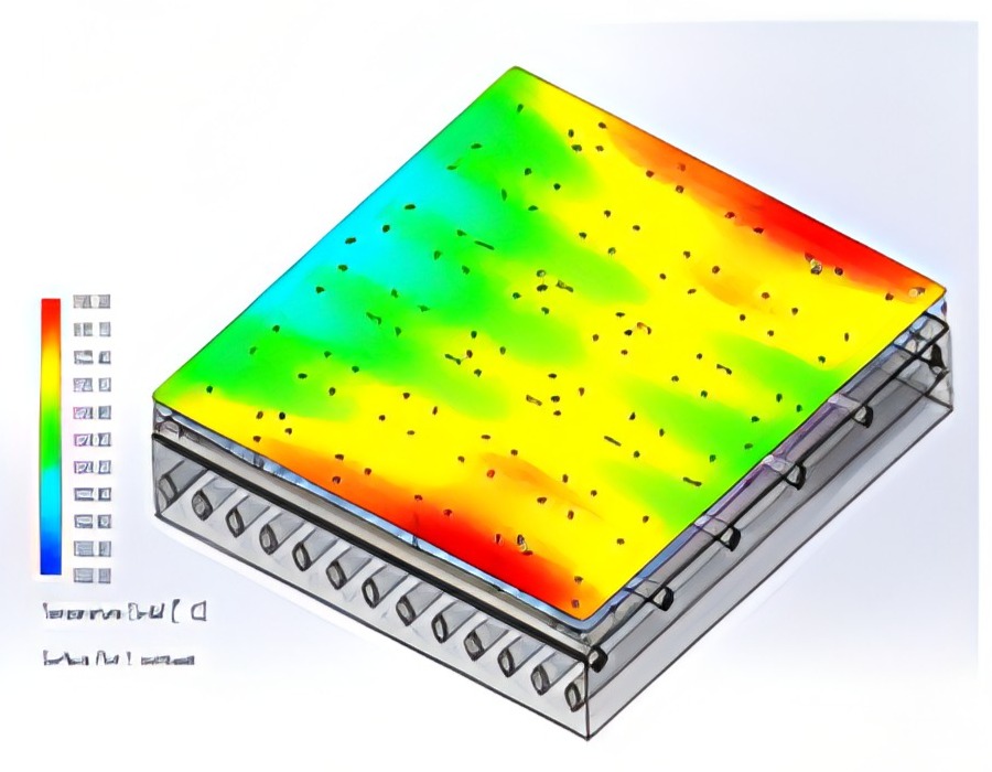
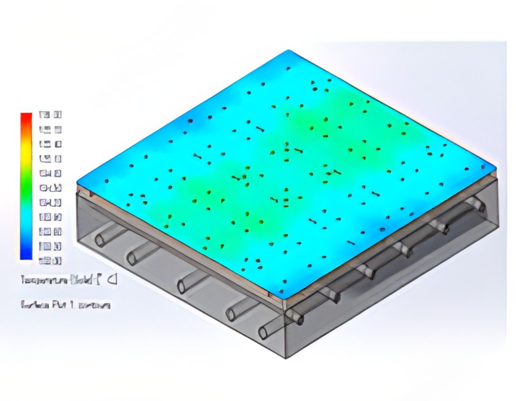
加熱装置の流体解析による、温度低下の原因解明
加熱装置の流体解析による、温度低下の原因解明で、外気影響による熱の損失を防ぎ、加熱炉単体の省エネに貢献。
加熱装置の流体解析による、温度低下の原因解明で、外気影響による熱の損失を防ぎ、加熱炉単体の省エネに貢献。
ヒアリング
シュミレーション条件ご提案
御見積り
モデル作成・解析
データ納品・ご説明
シュミレーション内容や3Dモデルご提供有無によって変わって参りますので、一度お打ち合わせをさせていただきまして、御見積りのご回答をさせていただきます。
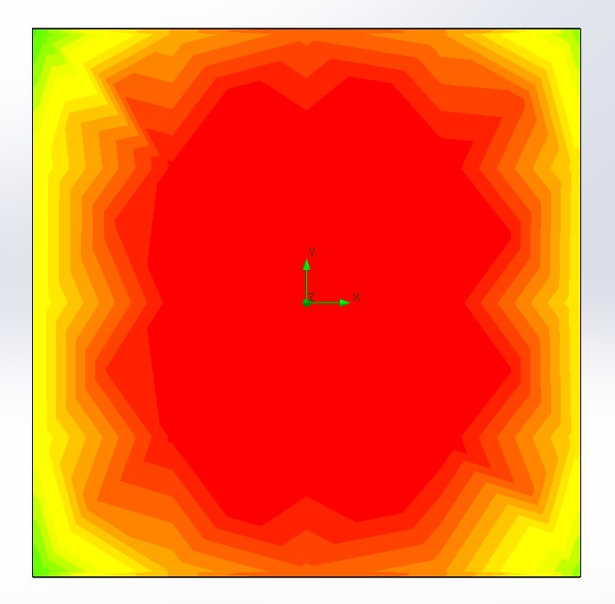
金属の温度分布や水・空気など流体の流れを解析することが可能です。
ヒーターブロックの表面温度分布の解析を実施し、その結果に基づいた設計変更やヒーター仕様変更に関するご提案も可能です。
解析対象となるものの3D図面がご提供いただけると納期や費用を抑えることが可能です。
また、どのような解析を実施なされたいのか具体的なご希望や条件などがあれば事前におまとめください。

営業拠点